Introduction
These
guidelines describe requirements regarding resistance measurement of joints,
and comprise measurement method and limit values for replacement of joints. The
purpose is to ensure that measurements are performed in the same way, that
measurement errors are minimized and that joints in bad condition are replaced
Scope
These
guidelines concern resistance measurement of joints. They cover how to perform
measurements, requirements on the measurement equipment and limit values for
replacement for joints
Definitions
Technical
terms and definitions used in this document:
Device
for joining two lengths of conductor to provide mechanical and electrical
continuity. Conductor here relates to phase conductor or shield wire. A joint
in a line span (mid-span joint or dead-end joint) has also, in addition to
electrical connection, the function of maintaining the full mechanical strength
of the conductor.
Compression joint
A
joint assembled by compression
Detonation compressed joint
A
compression joint compressed by detonation of an explosive charge wound around
the sleeve of the joint
Hydraulic compressed joint
Compression
joint compressed by a hydraulic tool
Screw joint
A
joint consisting of factory compressed sleeves on each conductor end, which are
joined by a screw sleeve
Bolted connector
A
joint or a clamp where contact is obtained by a bolted connection

Where
Rj
= is the resistance of the joint,
Rc
= is the resistance of the conductor per meter, read from datasheet,
Lj
= is the length of the joint in meters.
The
use of K – value has the advantage
of independence of conductor type and joint length
Temperature dependency of resistance
Specified
resistance values for conductors refer to 20O C. the same reference
temperature is applicable for the limit values specified in this document. The
following formula gives the resistance at other temperatures, if the resistance
at 20O C is known

Where
R20
= the resistance at 20O C
Rθ
= the resistance at temperature θ
θ
= the actual temperature
α= 0.004 for aluminum
(temperature coefficient)
A
temperature difference of 10 degrees corresponds to 4% resistance difference
for aluminum
Performing resistance measurement
General procedure
Concerning
full tension compression joins
Three
resistance values shall be measured: the whole joint R1, and the two
halves R2 and R3 is towards higher tower number

Figure 1 Joint Resistances
Apply
the clamps according to Figure 2; with the current clamps furthest out and the
measurement clamps on each side of the joint, and a measurement clamp on the
mid of the joint. The current clamps shall be placed at least 0.5 meter from
the joint. The measurement clamps on each side of the joint shall be placed 5mm
from the joint, but must not be in contact with the joint.

Figure: 2 Application of clamps, with a
photo as an example
Connect
the micro ohmmeter according to Figure: 3 from measurement of R1, R2
and R3 respectively
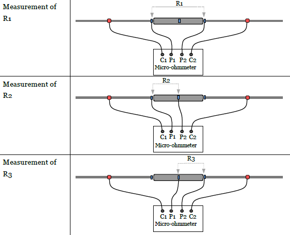
Figure:
3 Connection for measurement of R1, R2 and R3
Measurement
procedure for old joint or new joint on old conductor:
*Measurement
. Measure
the resistance R1
. Move
one measurement lead to the middle of the joint and measure R2
. Measure
R3 in the same way
. Note
the measured values,
*Loosen
the two measurement clamps on the conductor adjacent to the joint and rotate
them about 1/3 revolution
*Repeat
the measurement and note the values
*Loosen
the measurement clamps again and rotate another 1/3 revolution
*Repeat
the measurement and note the values
All measurement values shall be reported. The average
of the three measurements shall be compared with the applicable limit value.
Measurement
procedure for new joint or new conductor:
*As
above, but the measurement need not be repeated
Measurement
of special joint
Basic measurement principles are according to section
4.1
Compressed
dead end connector
For compressed dead end connector the resistance R1,
R2 and R3, according to Figure: 4, shall be measured. For
R1 and R3 the measurement procedure according to section
4.1 is applicable, with three repetitions. For R2 the measurement
need not be repeated.

Figure: 4 compressed dead end connector resistances
Screw
Joint
For screw joint the
resistance R1, R2, R3 and R4,
according to Figure: 5, shall be measured. For R1, R2 and
R4 the measurement procedure according to section 4.1 shall be
applied, with three repetitions. For R3 the measurement need not be
repeated

Figure:5 Screw Joint Resistance
Bolted
connectors
For parallel groove clamps and T-clamps the resistances
according to Figure 6 shall be measured. The measurements need not be repeated.

Figure 6 Bolted connectors resistances
Risks
for measurement errors
Insufficient
contact between conductor strands
The largest risk for errors in resistance measured on
old joints is due to old conductors often having bad contact between the
strands. This makes the measurement current unevenly distributed and may cause
large measurement errors, especially for joints that have an increased
resistance. The deviations can be both positive and negative.
Obtaining measurement values with good precision and
repeatability would require clamps that contact the whole circumference of the
conductor and at least 2 meters distance to the current clamps. Since this is
difficult to achieve in practice, we have chosen here a compromise, based on
three repeated measurements and moving the measurement clamps in between. The
resulting average value of the three measurements gives a reduction of the
error. In addition, the difference between the three measurements gives an
indication of the degree of this problem for each single case.
For new joints, on new conductors, this is normally not
a problem, and therefore repeated measurements are not required in this case.
Measurement of conductor resistance on old conductors
is also very uncertain, for the same reason. Therefore conductor resistance
should be taken from datasheets
Influence
of temperature
The temperature dependency of resistance is described
in section 3.
Regarding measurements on old joints, the temperature
effect is often negligible in comparison with other error sources. For new
joints the temperature may however significantly affect the comparison with the
required limit values.
The temperature can be accounted for by adjusting the
limit value to the prevailing ambient temperature. Possible solar heating may
be neglected.
A special case applies for measurement of newly
detonation-compressed joints, with remaining heat from the detonation. In this
case the surface temperature of the joint needs to be measured simultaneously
with the resistance measurement.
The use of instruments with built-in automatic
temperature compensation involves additional risks, e.g. due to erroneously set
values of temperature coefficient or reference temperature. The requirements
here applied for reporting of measurement values mean that such automatic
temperature compensation need normally not be used.
Joint
resistance
The following requirements apply to resistance at the
measurement occasion. These requirements shall be applied if nothing else has
been agreed on.
Requirements
for old mid-span joints
For old phase conductor mid-span joints, the limit
values in section 6.6 apply.
Joints that show higher measured resistance than the
limit value shall be replaced. This applies also if only one of the parts
exceeds the limit value.
For a screw joint, if the problem is in the screw
sleeve, this shall be corrected, after which a new measurement is made.
Requirements
for new mid-span joints
New
joint on new conductor
For new joint on new conductor reference is made to TR
05-07E, with the following additions.
The limit value shall be adjusted to the temperature of
the joint; normally the ambient temperature can be used.
For measurements of newly detonation-compressed joints,
with remaining heat from the detonation, the surface temperature of the joint
must be measured by a surface temperature probe simultaneously with the
resistance measurement.
New
joint on old conductor
For new joint on old conductor the resistance may not
exceed the type test value by more than 10 % + 2 μΩ. The same additions as
under 6.2.1 apply.
Requirements
for bolted connectors
New
bolted connector on new conductor
For new bolted connector on new conductor reference is
made to TR 05-15E.
New
bolted connector on old conductor
For new bolted connector on old conductor the
resistance may not exceed 0.6 times the corresponding conductor length (k =
0.6).
Old
bolted connectors
If measurement of an old bolted connector shows higher
resistance than the corresponding conductor length (k=1.0), the connector shall
be opened; brushed by a wire brush, coated by contact paste, brushed again and
reassembled, after which a new measurement is made.
Requirements
for dead-end joints
For dead-end joints, the limit values in section 6.6
apply for the compressions joints on line span conductor and on jumper
conductor. For the bolted jumper connection, the requirement according to
section 6.3 applies.
The dead-end joint shall be replaced if any of the
compression joints exceed the limit value. If the bolted jumper connection
exceeds the limit value, then it shall be corrected (see 6.3.3) after which a
new measurement is made.
Requirements
for joints on shield wires
For new joints on shield wires, the requirements
according to section 6.2 apply.
An old joint in a shield wire shall be replaced if the
measured resistance exceeds the limit value in section 6.7.
Limit
values for old joints on phase conductors
Table 1 lists limit values in the form of k-values as a
function of the highest continuous operating temperature of the line. Joints
constitute a higher risk, and age faster, at higher current load. Therefore the
limit values are stricter for lines operated at higher temperatures.
The limit values are for the reference temperature 20OC,
however, adjustment for the temperature at measurement need not be made for
measurements on old joints.
Table 1 Limit values for old joints, represented by
k-value.
Highest continuous
conductor temperature (OC)
|
K- Value
|
50
|
1.5
|
60
|
1.4
|
65
|
1.3
|
70
|
1.2
|
80
|
1.1
|
85
|
1.0
|
Limit values in micro-ohms can be obtained as: 𝑅= Rc×k×L
Where Rc = conductor resistance in μ/m (see Table 2)
k = k-value
L = the length over which the resistance is measured.
Table 2 contains listed values in micro-ohm/meter, i.e.
Rc×k, for joints on common conductors.
Table 2 Limit values in micro-ohm/meter joints on
common conductors, for different values of highest continuous conductor
temperature.
Conductor type, area
|
Conductor
resistance1 (µΩ/m)
|
Limit value for
joint, in resistance per meter (μΩ/m), at highest continuous conductor
temperature:
|
|||||
500C
|
600C
|
650C
|
700C
|
800C
|
850C
|
||
Dove, 329
|
102
|
153
|
143
|
133
|
122
|
112
|
102
|
Condor, 454
|
72
|
108
|
101
|
94
|
86
|
79
|
72
|
Curlew, 593
|
55
|
83
|
77
|
72
|
66
|
61
|
55
|
Morkulla,593
|
51
|
77
|
71
|
66
|
61
|
56
|
51
|
Martin, 772
|
42
|
63
|
59
|
55
|
50
|
46
|
42
|
Ripa, 774
|
39
|
59
|
55
|
51
|
47
|
43
|
39
|
Orre, 910
|
33
|
50
|
46
|
43
|
40
|
36
|
33
|
454AI59
|
65
|
98
|
91
|
85
|
78
|
72
|
65
|
774AI59
|
38
|
57
|
53
|
49
|
46
|
42
|
38
|
910AI59
|
33
|
50
|
46
|
43
|
40
|
36
|
33
|
593AIMgSi-B
|
52
|
78
|
73
|
68
|
62
|
57
|
52
|
774AIMgSi-B
|
40
|
60
|
56
|
52
|
48
|
44
|
40
|
910AiMgSi-B
|
34
|
51
|
48
|
44
|
41
|
37
|
34
|
1) DC resistance at 20 °C, from datasheet, rounded to
integer values.
Example of how to use Table 2:
For a joint on a Curlew-conductor, with measured length
0.81 m, and a highest continuous operating temperature of 50 OC, the
limit value is obtained as follows.
The distance between the measurement clamps, when
measuring R1, is 1 cm longer than the joint. This gives L = 0.82 m.
Table 2 gives the limit value 83 μΩ/m. This multiplied by L gives 0.82×83 = 68
μΩ. For R2 and R3, the length is L/2 and the limit value
half the value applied for R1. The limit values to be applied are:
R1: 68 μΩ
R2, R3: 34 μΩ.
Limit
values for old joints on shield wires
The following limit value, in the form of k-value,
applies for old joints on shield wires:
k= 2.0
Table 3 contains listed values in micro-ohms/meter. The
table is used as described in section 6.6.
Table 3 Limit values in micro-ohms/meter for joints on
shield wires, for common types of shield wires.
Conductor type,
area
|
Conductor
resistance 1 (μΩ/m)
|
Limit value for
joint, in resistance per meter(μΩ/m)
|
Dotterel, 142
|
323
|
646
|
Ibis, 234
|
143
|
286
|
Atle, 241
|
190
|
380
|
Ymer, 319
|
115
|
230
|
1) DC-resistance at 20 °C, from datasheet, rounded to
integer values.
Documentation
Required
content
Measurement protocols shall be delivered in
Excel-format and contain at least the following information:
* Measurement
performed by: Company and person
*Date
when the measurement was performed
*Identification
of measurement instrument: type and id-number
*Identification
of measurement object:
· Line
· Line designation
· Conductor type
· Highest continuous operating temperature
· Joint type (hydraulic compressed, detonation compressed, screw joint etc.)
· Length of the joint
* Ambient
temperature
*Limit
value applied
*Identification
of joint individual: Span no, Conductor no
*All
measurement values. Values larger than 10 µΩ may be rounded to integers
*Average
values of repeated measurements
*Commentary
field: any action taken, visual observations etc.
Example
of measurement protocol
Figure 7 gives an example of measurement protocol for
old joints.
Regarding measurement
protocol for new installations, reference is made to TR05-07E for joint and TR
05-15E for bolted connector
No comments:
Post a Comment